
FIELD NOTE
Type: Field Report / Maintenance Planning
Related Project: Ham Radio
System Status: Operational; modernization and hardening planned
Date / Time: July 25, 2026; Arizona time
Location / Environment: Banner Del E. Webb Medical Center, Sun City West, Arizona; fourth-floor elevator machine room and roof-mounted antenna mast
Equipment / Software: Yaesu DR-2X repeater; Arcom RC-210 controller; cavity duplexers; Raspberry Pi AllStar node; Yaesu FTM-300D; Yaesu HRI-200; Dell OptiPlex control computer; Linksys networking equipment; PoE injector; Ubiquiti wireless bridge
Outcome: The visit confirmed that NY7S is a compact multi-system communications facility, not merely a repeater in a rack, and identified practical work to improve mounting, labeling, cable management, power protection, environmental and electrical monitoring, scheduled maintenance, recovery, and long-term serviceability.
Last Verified: July 28, 2026, from club-provided system information and the supplied repeater listings
After nearly 30 years in broadcast video engineering, I have spent a lot of time around equipment racks. Television studios, production trucks, control rooms, temporary show systems, and remote facilities all depend on the same fundamentals: stable power, secure connections, clear labels, documented signal paths, and a system that can be serviced without causing a second failure.
When Josh Cavender, KE7WIL, invited me to visit the West Valley Amateur Radio Club’s NY7S repeater site, I expected a repeater, a controller, and perhaps a small computer supporting the AllStar node. What I found was a small communications facility packed into a six-foot equipment rack.
Getting to the Repeater
Josh and I met at Banner Del E. Webb Medical Center in Sun City West. A member of the hospital maintenance staff escorted us to the fourth-floor elevator machine room, where the repeater equipment and roof access are located.
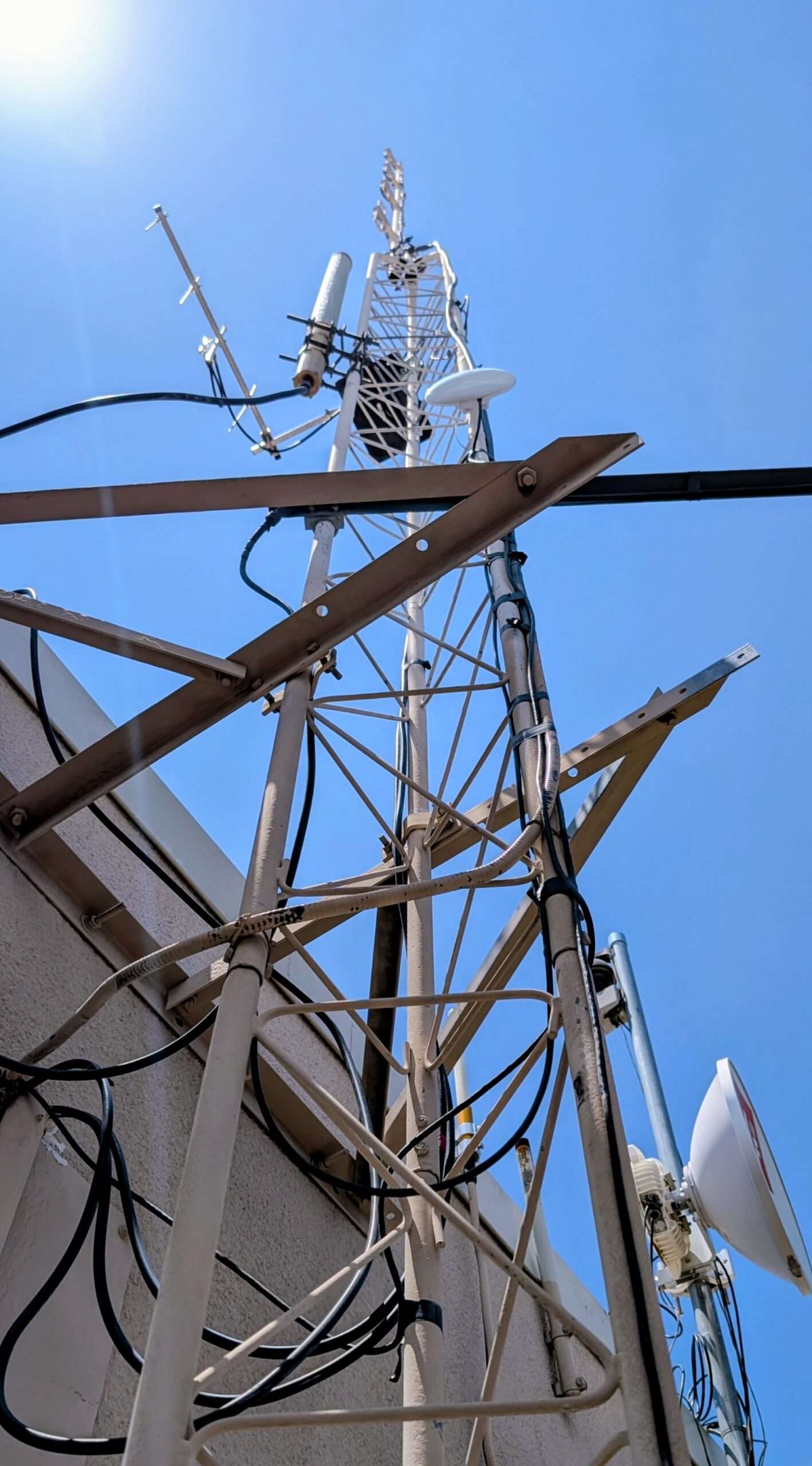
The elevator machine room is not what most people imagine when they think of a radio station, but it is a practical location. It provides protected indoor space for the rack, access to power, and a path to the antennas above the roof. From there, the NY7S mast rises approximately 28 feet, with a roughly 20-foot antenna attached at the top.
Before Josh opened the rack, I expected a relatively compact installation—perhaps a two-rack-unit repeater with a controller and a Raspberry Pi. That expectation disappeared immediately.
More Than a Repeater
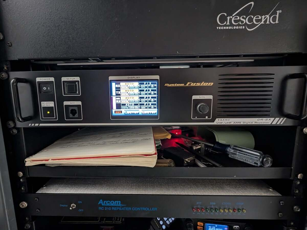
The rack contains the NY7S repeater, its controller, supporting RF hardware, computers, network equipment, power supplies, the AllStar node, and the hardware that connects the W7JHQ repeater at Boswell Medical Center to WIRES-X.
What first looked like one repeater was actually a collection of RF, computer, control, and network systems working together. Every available part of the rack appeared to have a job.
WVARC Repeaters & Nodes
DEL WEBB — NY7S
147.3 MHz (+) | PL 162.2 Hz | FM
AllStar Node 63916
EchoLink Node 598882 / NY7S-R
BOSWELL — W7JHQ
449.8 MHz (-) | PL 100.0 Hz | Fusion and FM
WIRES-X Room 81854
The Cavity Duplexers
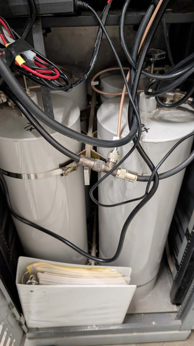
One of the most impressive parts of the installation is also one of the least obvious from the front: the cavity duplexers.
A repeater must receive a weak incoming signal while transmitting a much stronger signal only 600 kHz away. Without enough isolation, its own transmitter would overwhelm the receiver every time the system keyed up.
The large tuned cavities provide that isolation. They separate the transmit and receive paths while allowing both frequencies to use the same antenna. Compared with the radios and computers, the cavity duplexers are physically enormous, but that size is part of what makes the filtering possible at VHF.
Connecting W7JHQ to
WIRES-X
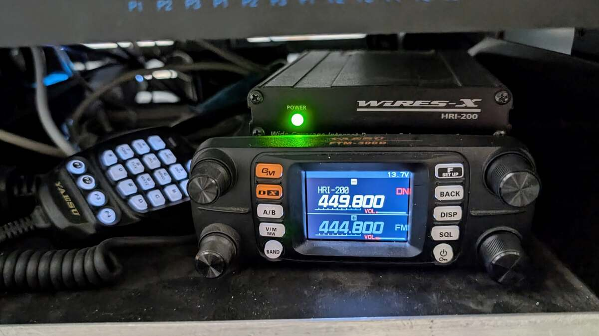
The Del Webb site also supports the W7JHQ System Fusion repeater at Boswell Medical Center. A UHF antenna mounted on the NY7S mast provides a radio bridge between Boswell and Del Webb. At the Del Webb end, a Yaesu FTM-300D and HRI-200 connect that RF path to WIRES-X.
The linking radio displayed 449.800 MHz and 444.800 MHz, corresponding to the W7JHQ repeater’s output and input frequencies. This arrangement places the Internet-connected WIRES-X equipment at Del Webb while the W7JHQ repeater remains at Boswell.
Internet by Radio
The Internet connection at NY7S is also delivered over a radio link. A Ubiquiti wireless bridge mounted on the NY7S mast connects the repeater site to KC0UU’s ham shack.
At Del Webb, a Power over Ethernet injector supplies power to the mast-mounted Ubiquiti equipment. Linksys networking hardware and a Dell OptiPlex control computer support the local network and site-control functions.
KC0UU’s ham shack
        ↓ Ubiquiti wireless bridge
NY7S mast and rooftop radio
        ↓ PoE injector
Local network, control computer, AllStar, and WIRES-X equipment
In broadcast engineering, we would describe that as backhaul. The transport method is different, but the purpose is familiar: move control and communications traffic reliably between facilities.
The Back of the Rack
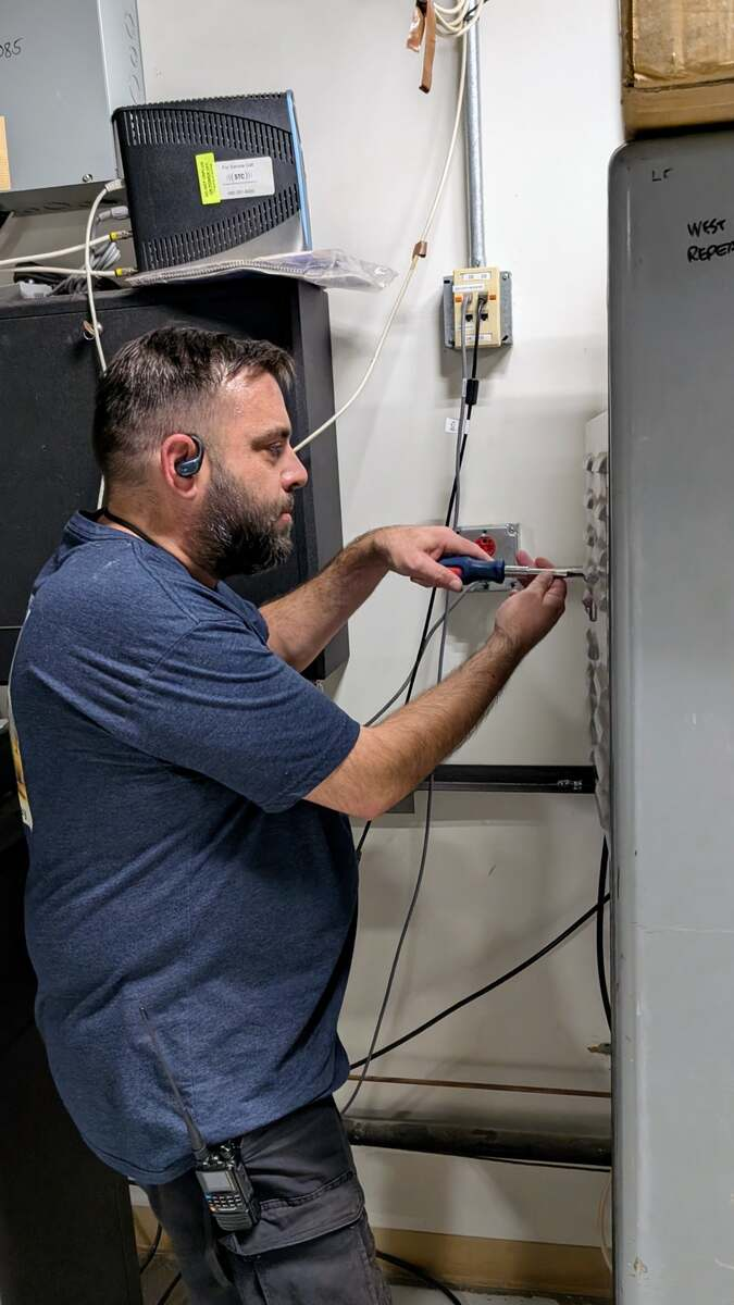
Once we moved behind the rack, my broadcast-engineering instincts took over.
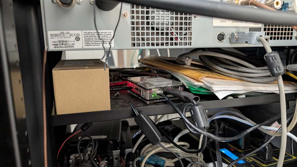
The system has clearly grown as new capabilities were added. RF feed lines, control wiring, USB interfaces, Ethernet, AC power, DC power, adapters, and power supplies all converge inside a limited amount of space. The equipment is operational, but several connections are mechanically fragile and the cabling needs a deliberate service plan.
During the inspection, I lightly disturbed a USB cable and temporarily took the AllStar node offline. We restored the connection, but the incident demonstrated how easily routine maintenance could interrupt service.
Long-lived technical systems often develop this way. A working installation receives another feature, then another interface, then a replacement computer or temporary adapter. Each addition solves an immediate problem, but the combined system becomes harder to understand and service.
The next phase should make the installation more robust, not simply add another box.
Replacing the AllStar Node
The current AllStar node uses a Raspberry Pi connected through USB interface hardware. We are considering two broad replacement paths: a Raspberry Pi 5 or another Dell micro computer with more processing headroom.
Raspberry Pi 5
A Raspberry Pi 5 would keep the node compact and relatively low-power. It could be securely mounted on a rack shelf, powered from a managed supply, and paired with a prepared replacement storage device or complete spare node.
The strength of this approach is field replacement. If the node is standardized and documented, a failed unit could be exchanged without rebuilding the entire system during an outage.
Dell Micro Computer
A Dell OptiPlex Micro or similar x86 computer would provide conventional SSD storage, more memory, and additional capacity for logging, monitoring, remote administration, and future services.
The Dell would consume more power and occupy more space, but the platform is familiar, serviceable, and readily available. It may also offer useful firmware behavior such as automatically restarting after power is restored.
The final decision should be based on reliability rather than benchmark performance. An AllStar node does not need to win a computing contest. It needs to boot every time, recognize its interfaces, recover after an interruption, and remain stable for long periods without attention.
Hardening the System
In broadcast engineering, the device that fails is not always the most complicated equipment in the room. Failures frequently happen at the edges: a connector works loose, a wall adapter is unplugged, a USB device fails to return after a reboot, or a cable cannot be traced because neither end is labeled.
Secure Mounting and Strain Relief
Computers, interfaces, network devices, and power supplies should be mounted to shelves or panels instead of resting loosely on other equipment. USB, Ethernet, power, and controller connections need strain relief so cable weight or routine service cannot pull directly on a connector.
Cable Management
The rack should be dressed by function where practical:
- RF and coaxial cables
- AC power
- DC power
- Ethernet
- USB
- Audio and repeater-control wiring
- Antenna and mast connections
The goal is not cosmetic perfection. The goal is serviceability: each cable follows an understandable route, has enough service loop to permit maintenance, and does not place stress on a connector.
Labeling
Every cable should be labeled at both ends. Labels should identify source, destination, and purpose. Power supplies and wall adapters should identify the equipment they serve. USB interfaces should be marked so they can be returned to the correct ports.
A technician should be able to open the rack and understand a connection without tracing it through the entire cabinet by hand.
Documentation
The finished installation should include:
- A rack elevation
- A signal-flow diagram
- A network diagram
- A power-distribution map
- Controller port assignments
- An equipment inventory
- Current configuration backups
- Recovery instructions
- Contacts responsible for each subsystem
Documentation turns individual knowledge into club knowledge.
Power Protection
The computers, network equipment, PoE injector, and Internet-connected interfaces would benefit from UPS protection or another site-approved backup-power arrangement.
Even where generator power is available, a brief interruption during transfer can reboot computers and networking equipment. A UPS could bridge that transition and help the control systems remain online or recover cleanly.
The transmitter itself may require a larger and more specialized backup system. Protecting the lower-power computing and network infrastructure is a practical first step.
Room Temperature Monitoring
The repeater lives in an elevator machine room, not a purpose-built broadcast equipment room. The site needs continuous temperature monitoring so the club can see whether the room or rack is gradually running hotter, detect a ventilation or air-conditioning problem, and respond before heat begins shortening the life of power supplies, computers, network equipment, or the repeater itself.
A practical first system does not need to be elaborate. One sensor should measure the room near the rack, and a second sensor near the rack inlet or upper equipment area would show whether heat is building inside the cabinet. Readings should be logged, compared with a normal seasonal baseline, and tied to simple warning and critical alerts. Alert limits should follow the equipment specifications and the actual baseline established at the site rather than an arbitrary one-size-fits-all number.
DC Voltage and Current Monitoring
The main DC supply should also be monitored for voltage and current. A low supply voltage, excessive voltage drop, an aging power supply, or an unexpected increase in current draw can provide early warning of a problem before equipment fails outright.
On a volunteer budget, the sensible starting point is to monitor the main DC bus and any critical branch that can be measured cleanly without adding a maze of new failure points. The repeater, controller, linking radio, and other major DC loads should have documented normal readings at idle and during transmit. Future maintenance visits can compare current measurements with that baseline and investigate meaningful changes.
The monitoring system should be useful without becoming another fragile subsystem. It should provide local readings, retain enough history to show trends, and send remote alerts when practical. A handheld meter and a written baseline remain the fallback when the monitoring computer or network is unavailable.
Automatic Recovery and Monitoring
The replacement node should be tested for automatic recovery after:
- Loss and restoration of commercial power
- Loss and restoration of Internet connectivity
- A disconnected or reconnected USB interface
- A software crash
- An unexpected reboot
Remote monitoring should verify the AllStar service, network bridge, control computer, UPS, room temperature, rack temperature, DC voltage, and DC current where practical. Monitoring is useful only when someone receives the alert, understands what it means, and knows the first recovery steps.
Scheduled Maintenance
Remote monitoring is not a substitute for putting hands on the system. The repeater should have a written quarterly, semi-annual, and annual maintenance routine, with every visit recorded in a simple site log.
Quarterly: Physical Site Check
- Visit the site and compare the local temperature, DC voltage, DC current, UPS, network, AllStar, and WIRES-X readings with the remote dashboard and the established baseline.
- Inspect connectors, USB interfaces, power plugs, coax jumpers, cable supports, strain relief, labels, shelves, fans, and visible grounding connections.
- Look and listen for heat, dust buildup, unusual fan noise, loose hardware, damaged insulation, discoloration, odor, or anything else that has changed.
- Verify the repeater, AllStar, EchoLink, WIRES-X link, Ubiquiti bridge, and remote-control paths are operating as expected.
- Resolve small issues during the visit when it is safe to do so, and record anything requiring parts, approval, or a scheduled outage.
At least one quarterly inspection can be coordinated with the club’s EmComm event preparation. If the repeater is part of the communications plan, verifying the repeater and its supporting infrastructure should be part of the exercise rather than a separate afterthought.
Semi-Annual: Recovery and Backup Check
- Test UPS status and a controlled power-transfer scenario using a site-approved procedure.
- Confirm that computers, network equipment, the AllStar node, and linked services restart or remain online as designed.
- Verify current configuration backups and prove that the spare node, spare storage device, or replacement computer can boot and reach a known-good state.
- Review alarm delivery, contact information, remote access, passwords, and recovery instructions.
- Clean accessible vents, fans, and shelves without disturbing cavity duplexer tuning or critical RF connections.
- Review the equipment and spare-parts inventory, replacing only what is genuinely missing or unreliable.
Annual: Full System Review
- Perform a deeper RF and operational review with the appropriate test equipment and qualified club members.
- Verify transmitter output, receive performance, audio or deviation, antenna-system condition, and feed-line performance as appropriate.
- Check cavity duplexer performance if measurements indicate a problem; do not casually retune a working duplexer as routine housekeeping.
- Review the rack elevation, signal-flow diagram, network diagram, power map, controller assignments, maintenance log, and recovery documentation.
- Review battery age, power-supply condition, fans, surge protection, and other wear items.
- Set the next year’s priorities and budget based on actual risk, measured performance, and volunteer capacity.
The schedule should remain realistic. Missing an ambitious checklist because it requires a full engineering crew helps nobody. A short quarterly visit that actually happens, with a consistent log and clear follow-up, is more valuable than a perfect maintenance plan that exists only on paper.
Redundancy Without Unnecessary Complexity
Redundancy does not always require duplicating every component. For the AllStar node, a practical backup may be a fully configured spare computer or storage device ready for installation. Configuration backups should be stored away from the site, and common failure items should be kept as labeled spares.
A full secondary Internet path may eventually be worth considering because the Ubiquiti bridge is critical to the site’s Internet services. That would be a larger project. The first step is documenting the current path and understanding which single points of failure have the greatest operational impact.
The best backup system is one that can be tested, maintained, and understood by more than one person.
Volunteer Engineering on a Shoestring
This is a volunteer-operated club system. Much of the equipment has been donated, the budget is finite, and every improvement competes with other club needs. The answer is not to recreate a commercial broadcast facility one purchase order at a time.
The practical target is a system that is reliable, understandable, repairable, and affordable. That means reusing known-good equipment where it makes sense, choosing common parts that can be replaced easily, using open-source monitoring and documentation tools, and spending money first on the failures most likely to take the site offline.
- Prefer one simple, documented monitoring system over several clever but unsupported gadgets.
- Use existing Raspberry Pi or Dell hardware when it is dependable and can be mounted properly.
- Standardize cables, power supplies, storage devices, and spare parts where possible.
- Buy reliability before performance: secure mounts, labels, strain relief, a UPS, and tested backups usually matter more than a faster processor.
- Make upgrades in phases so each completed step leaves the site better than it was before.
- Document donated equipment and verify it before it becomes a critical component.
- Design the system so another club member can maintain it without needing the original installer standing beside them.
Frugal does not mean improvised forever. It means putting limited money and volunteer hours where they reduce the most risk.
Preparing Before It Matters
Amateur repeaters support daily nets, conversations, announcements, and club activity. They become even more important when normal communications are disrupted.
Emergency reliability is not created during the emergency. It is created beforehand through maintenance, documentation, testing, spare equipment, and careful engineering.
My first visit to NY7S changed how I thought about the site. It is not simply a radio mounted in a hospital. It is a continuously operating communications facility connecting local operators, Internet-linked networks, and another repeater location.
The equipment already provides substantial capability. The next task is to make the supporting infrastructure as reliable, serviceable, and understandable as the radio system deserves.
In broadcasting, the audience should never have to think about the equipment behind the program. For a repeater, the goal is much the same: press the push-to-talk button and have the system work—especially on the day when it matters most.
Next Actions
- Inventory every device, interface, power supply, and cable in the rack.
- Create a rack elevation, signal-flow diagram, network diagram, power map, and maintenance log.
- Choose and bench-test the replacement AllStar platform: Raspberry Pi 5 or Dell micro computer.
- Install simple room-temperature and rack-temperature monitoring with trend logging and actionable alerts.
- Add DC voltage and current monitoring for the main bus and critical loads where it can be done cleanly.
- Validate automatic recovery after power, network, USB, and software interruptions.
- Install UPS protection for the computer, network, PoE, and interface equipment where approved.
- Mount loose equipment, add strain relief, dress the cabling, and label both ends of every connection.
- Prepare a complete backup and a tested spare-node recovery plan.
- Create quarterly, semi-annual, and annual checklists and assign an owner for each scheduled visit.
- Coordinate at least one quarterly physical inspection with the club’s EmComm event preparation.
- Prioritize each improvement by outage risk, cost, donated resources, and available volunteer hours.
Sources and References
- RepeaterBook — NY7S, Del Webb
- RepeaterBook — W7JHQ, Boswell
- West Valley Amateur Radio Club Website
- Site observations and photographs from the July 25, 2026 visit with Josh Cavender, KE7WIL.
FIELD DISCUSSION
Discussion
Comments submitted here and replies received through ActivityPub-compatible networks are collected in the same thread.
FEDIVERSE RESPONSE
Fediverse Reactions