
FIELD NOTE
Type: Configuration / Instruction
Related Project: Ham Radio
System Status: Operational
Date / Time: July 13, 2026; Arizona time
Location / Environment: Bench or installed antenna system
Equipment / Software: SeeSii NanoVNA-F V2, device firmware V0.6.2, 4.3-inch display, 50 kHz–3 GHz range, Nano VNA-F V2 User Guide Rev. 2.0, Open/Short/Load calibration standards, antenna and feed line
Outcome: A calibrated S11 sweep provides a repeatable SWR measurement across the antenna’s operating band.
Last Verified: July 13, 2026
Summary
The SeeSii NanoVNA-F V2 is a dual-port portable vector network analyzer with a 4.3-inch IPS display, SMA connectors, a 50 kHz–3 GHz measurement range, four traces, four markers, and seven calibration save slots. The unit used for this procedure is running firmware V0.6.2. For antenna work, its most useful functions are SWR, return loss, impedance, Smith chart display, cable loss, and TDR.
Connect the Antenna
Disconnect the antenna feed line from the radio and connect it to PORT 1 / TX on the NanoVNA-F V2. PORT 2 / RX is not used for a basic one-port antenna SWR measurement. Never connect the NanoVNA to an energized transmitter.
Set Up the Sweep
- Open STIMULUS.
- Set START and STOP for the band being tested. Use 144–148 MHz for 2 meters or 420–450 MHz for 70 centimeters.
- Open DISPLAY → TRACE and activate a trace.
- Set that trace to S11 using DISPLAY → CHANNEL.
- Set the format to SWR using DISPLAY → FORMAT → SWR.
Calibrate PORT 1
- Open CAL → CALIBRATE.
- Connect the OPEN standard to PORT 1 and select OPEN.
- Replace it with the SHORT standard and select SHORT.
- Replace it with the 50-ohm LOAD and select LOAD.
- Select DONE.
- Save the calibration to one of the seven available save slots.
When a test cable or adapter is used, perform Open/Short/Load calibration at the far end of that cable. The calibration plane must be the same point where the antenna feed line will be connected.
Measure the Antenna
- Replace the 50-ohm load with the antenna feed line.
- Open a marker through MARKER → SELECT.
- Move the marker to the intended operating frequency.
- Record the SWR and the frequency of the lowest point in the trace.
Read the Result
| SWR | Practical interpretation |
|---|---|
| 1.0–1.5:1 | Very good match |
| 1.5–2.0:1 | Generally usable |
| 2.0–3.0:1 | Investigate before sustained high-power use |
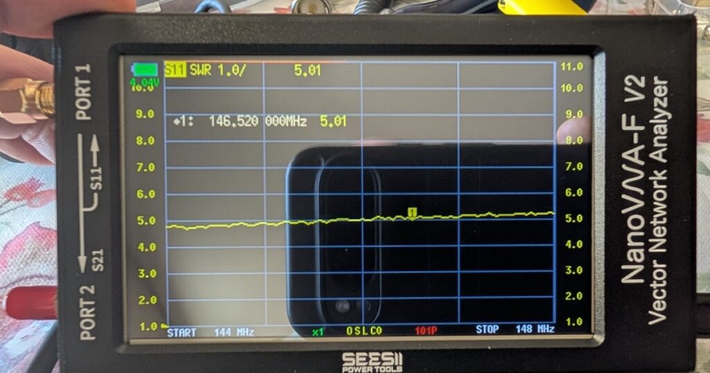
| Above 3.0:1 | Likely tuning, feed-line, connector, mount, or grounding fault |
The lowest point shows where the installed antenna system is best matched. A dip below the desired frequency usually indicates an antenna that is electrically too long; a dip above it usually indicates one that is too short.
Important Limits
A good SWR reading confirms an acceptable impedance match. It does not prove that the antenna has a good radiation pattern, low vehicle noise, correct polarization, or useful range. For a mobile installation, measure from the radio end of the feed line so the result includes the antenna, mount, connectors, and coax.
The available manual is Rev. 2.0 for firmware V0.3.0, while the tested device runs V0.6.2. The core S11, SWR, marker, and Open/Short/Load calibration workflow remains applicable, but menu placement or labels may differ slightly.
Sources and References
- Nano VNA-F V2 Portable Vector Network Analyzer User Guide, Rev. 2.0, written for a different manufacturer. Uploaded project manual.
- Observed device firmware: V0.6.2.
- SeeSii NanoVNA-F V2 product listing: 4.3-inch portable vector network analyzer, 50 kHz–3 GHz.
- Yaesu FTM-510DR/DE manual — uploaded site copy: antenna installation guidance specifies a 50-ohm antenna and coax, with VSWR adjusted to 1.5 or less where practical.
FIELD DISCUSSION
Discussion
Comments submitted here and replies received through ActivityPub-compatible networks are collected in the same thread.
FEDIVERSE RESPONSE